INTERMODULATION METER
BLOCK DIAGRAM

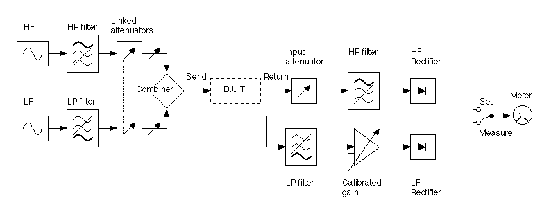
Two tones, one high and one low, are generated by separate oscillators and combined in a way that ensures they do not interact. The combined signal is passed through the Device Under Test.
The return signal is attenuated to a standard level and filtered to remove the low frequency signal, the remaining high frequency signal is rectified. If any intermodulation has occurred, the amplitude of the high frequency signal will have ripple at the low frequency superimposed on it. This low frequency ripple is passed through a filter which removes any residual high frequency, further amplified by an accurately known amount, and detected. The ratio of the ripple to the high frequency signal is a measure of the intermodulation which has occurred.
In normal operation, the combined signal is set to a suitable level for the device under test. The level of the returning signal is measured with the meter in the SET position and the input attenuator is adjusted in coarse and fine steps until the meter indicates a reference level. The meter is then switched to MEASURE and the gain of the low frequency ripple amplifier adjusted in steps until the meter reading is on scale. The meter reading is added to the accurately-calibrated amplifier gain step to get the level of intermodulation in units of dB.
This type of distortion meter is particularly advantageous for testing recording devices, where the returning signal may not have exactly constant frequency. The intermodulation distortion figure is not directly comparable to Total Harmonic Distortion percentage, but the following table can be used as a rough guide:
|
|
|
|
|
|
|
|
|
|
|
|
|
|
|
|
|
|
|
|