RECORDGRAPH
A sound recording and reproducing system

The Recordgraph system of recording was developed by Fredrick Hart & Co. of New York some time in the late 1930s. And was described in an article in the S.T.C Journal, January 1941 by W. L. Woolf.
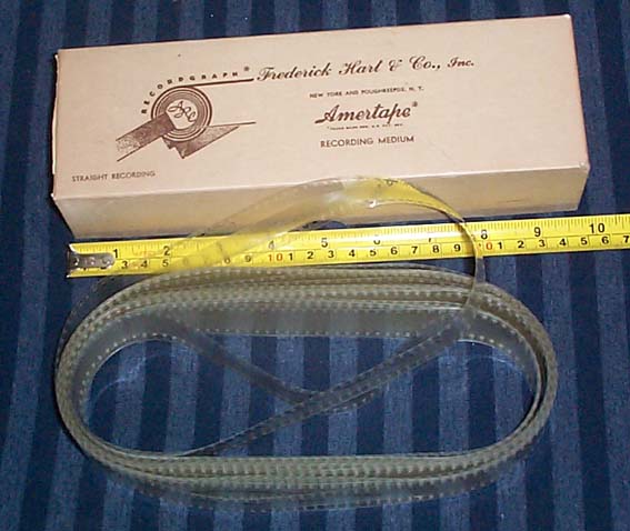
It uses uncoated 35mm Cellulose Acetate film, into which a laterally-modulated groove is embossed. The 'endless' film loops usually comprise 50 ft [15.24 m] of film, wound as a hank of 30 turns. This is loaded onto a magazine from which it is drawn from the centre, through the mechanism of the machine, by a sprocket wheel. During recording, the film is embossed with a sound-track in the form of a groove and then returned to the outside of the magazine. The standard recording speeds are 20, 40 and 60 feet per minute (4, 8 & 12 ips) [ 10.2, 20.4 & 30.6 cms/sec].
After one complete run through the loop, a series of scallops in the edge of the film operate an electrical contact which starts a tracking motor. This drives the carriage, which supports the recording and playback heads, across the width of the film for a distance of 0.01" [0.25mm]. The groove continues to be recorded, but is now displaced sideways from the starting alignment, so it does not cut into the existing recording.
This process continues, with the groove being displaced at each full turn of the loop, until 100 grooves have been recorded across the width of the film. By this means, a continuous recording lasting several hours can be made. A double playing time can be obtained if the film is twisted by 180 degrees, before being spliced, to form a Moebius Loop which allows recording on both sides alternately.
Playback is by means of a stylus mounted in a gramophone-type pickup head. This is mounted on the tracking carriage and moves sideways in a similar way to the recording head. It can be used during recording for immediate playback.
 |
|
|
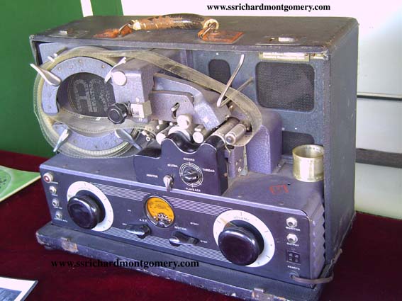
(front view) |
Picture courtesy of www.ssrichardmontgomery.com |
|
|
|
|
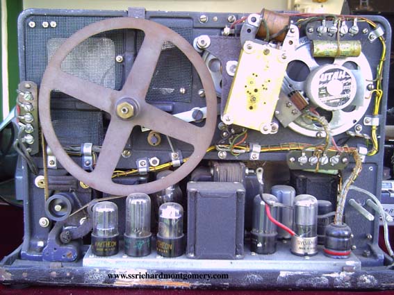
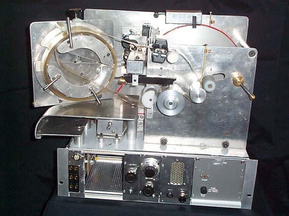
(back view) |
Picture courtesy of www.ssrichardmontgomery.com |
|
|
|
|
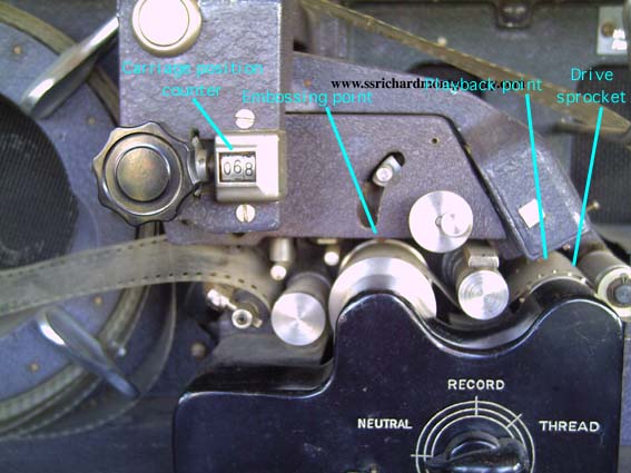
showing the recording and playback mechanism |
Picture courtesy of www.ssrichardmontgomery.com |
|
|
|
|
|
|
|
|
|
|
|
|
A New Recordgraph Playback Machine
|
The film is assumed to have become embrittled to some
extent during storage and must not be subjected to tight
bending during the playback process. It was stored in long
narrow boxes with approximately 25mm radius bends at the
ends, so bends in the direction of storage may be tighter
than those in the opposite direction for the same
stresses. |
|
 |
|
|
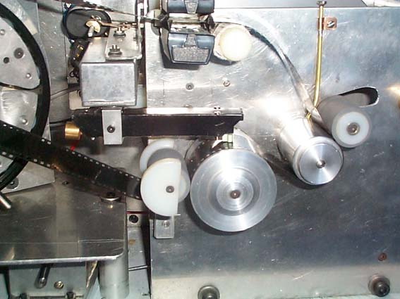
(Threaded with black film for clarity) The brake pressure roller has nylon guide cheeks with 39 mm spacing to allow bulky repairs and reinforcements to the film to pass through easily. The pickup arm is suspended from a die-cast box on a carriage which is tracked by a servo motor to follow the pickup position on the film. An optical mechanism inside the die-cast box controls the motor so that the pickup tracks correctly. The pickup is made from a composite structure with high internal damping, consisting of 5mm thick 3-ply wood with a cladding of 0.005" [0.127mm] aluminium alloy (lithography plate) bonded with bitumen mastic. The cartridge is a Shure M44C with a 0.002" conical stylus trailing at 30 degrees from the vertical. A counterbalance weight is set to give a tracking weight of around 5 gms. |
|
 |
|
|
The main drive motor is partly visible underneath the magazine platform. It drives the 10" [254mm] diameter flywheel by means of a red-coloured polyurethane belt. A magnetic tachometer pickup, mounted above the flywheel, detects a pattern of magnetic ink bars printed on an acetate strip which is attached to the flywheel rim. The flywheel speed is compared with the setting of a 10-turn calibrated potentiometer and a correction signal derived, this is used to control the motor speed. The flywheel drives the capstan by means of a shaft which is supported by a pair of silent-running sleeve bearings in self-aligning resilient mountings with internal lubrication reservoirs. Lubricating oil is introduced to the main bearings through supply pipes from remote oil cups, so as to reduce the possibility of oil spillage finding its way onto components which come into contact with the film. The rubber-sleeved nylon pressure rollers run freely on polished silver-steel stub shafts and do not require additional lubrication. The replay anvil/braking capstan is mounted on the shaft of a four-pole skewed-rotor A.C. induction motor with a single silent-running sleeve bearing. When fed with D.C., this provides smooth braking torque which is made adjustable by means of a control knob adjacent to the speed control. The magazine comprises a circle of free-running nylon rollers which support the film loop, one roller at the draw-off point being of larger diameter than the others to reduce bending stresses where the film is pulled from the magazine. The body of the magazine is split, with the upper portion fixed and the lower portion swinging on a pivot so as to permit easier loading and to accommodate film loops which may have attained a non-standard length through shrinkage. An adjustment screw allows a controlable amount of slack to be maintained when running delicate films. The whole magazine can be easily detached by means of a knurled nut (not visible) to simplify loading and unloading and to reduce the risk of snagging the film and damaging it. The magazine platform is curved to allow non-standard film loops to be suspended freely, if they will not fit the magazine, and fed into the mechanism from below. The lever towards the top RHS allows the pressure rollers to be disengaged and swung clear during loading. A velvet-sleeved finger (top) wipes dirt from the surface
of the film after each pass through the mechanism and this
is followed by a pair of carbon fibre brushes to discharge
static electricity from both surfaces before the film is
returned to the magazine. |
Whilst the information on this website is believed to be correct, no responsibility can be taken for its accuracy or otherwise. This is not an official website for any organisation other than Poppy Records.